Why Raymarching?
People are generally familiar with the more common rendering techniques of rasterization and raytracing. Rasterization is by far the most common, used in most applications to achieve performative real-time rendering. Raytracing is commonly found where realism is the focus, such as movies, where rendering the scenes can take many hours.
For this project, I wanted to investigate a lesser known but extremely useful technique called Raymarching. It began with a question I had about shapes like fractals or clouds - shapes that cannot easily be defined by triangles, which is the fundamental building block in both rasterization and raytracing.
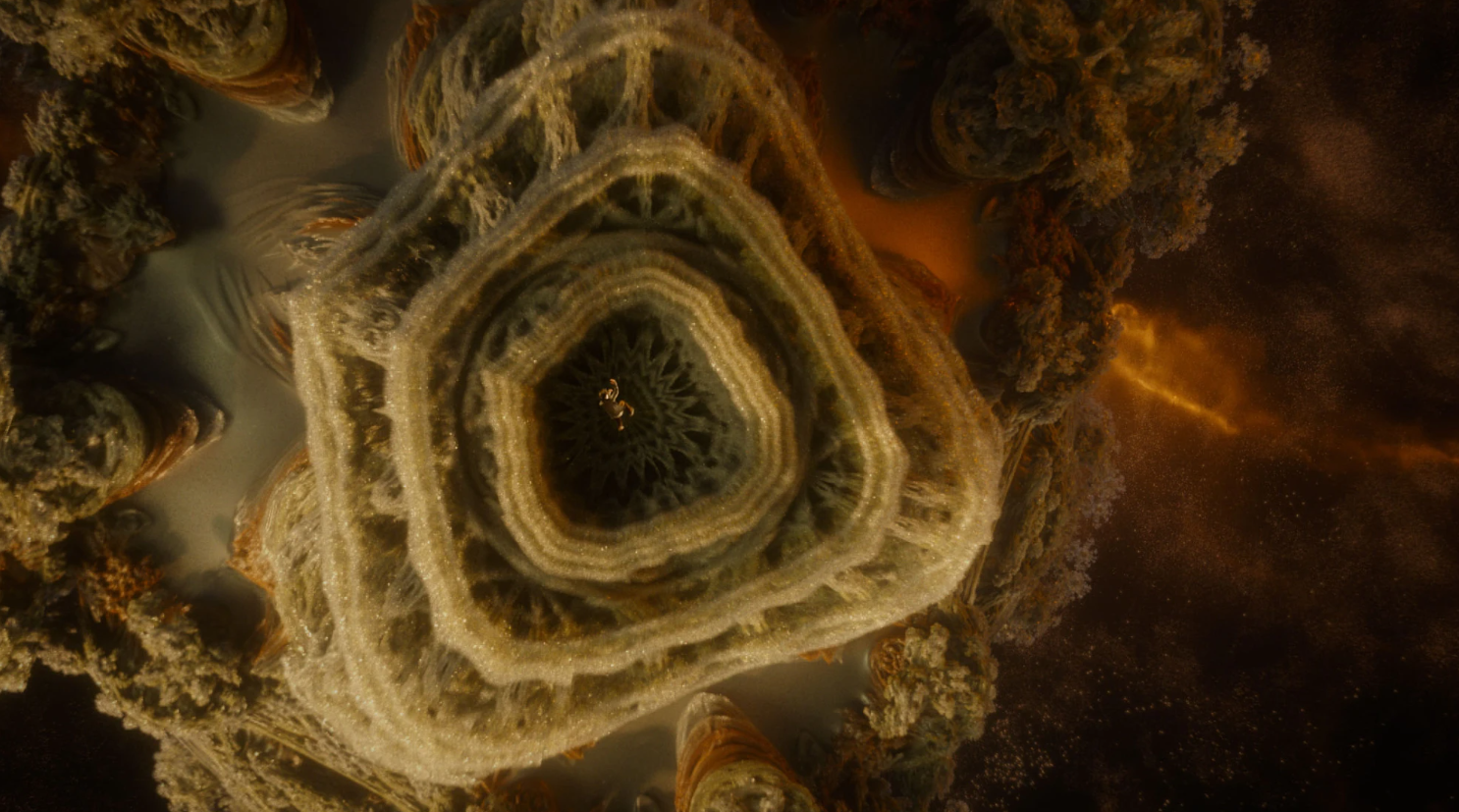
 In a similar fashion to raytracing, raymarching shoots out many rays from the camera origin out into the scene. What’s different is that for raymarching, every object in the scene has a signed distance function (SDF), which, for any given point in the scene, can calculate how far the object is from that point. This allows us to know, for any point, the radius of a sphere centered on the point in which there is guaranteed to be no intersecting objects.

This diagram displays the concept in two dimensions, which is easily extended to 3D. After calculating the minimum distance, we can move our point to the edge of the sphere (hence, marching), repeating the process until an object is hit. To determine whether we have hit an object, a small tolerance is defined (such as 0.001), and if the minimum distance is smaller than that, we have hit something in the scene.
 To explore this concept, I used Unreal Engine 5’s built-in materials with a custom node that allows HLSL code to overwrite what is rendered to the screen. A sphere has the simplest SDF:
 distance = length(point - radius). In addition to this, you can calculate normals from a hit by adding small epsilon offset in the X, Y, Z planes to the SDF calculation and normalizing it. This can be considered the “hello world” of raymarching. Also, whether or not a ray hits an object determines opacity of the object. Finally, I added some basic ambient, diffuse, and specular lighting that I learned from my previous raytracing study to get the image you see above.
The neatest part of this is that all the work has been done already. We can have any shape we want out of the box, as long as we have the SDF for it.
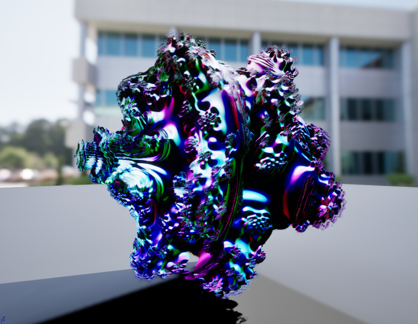
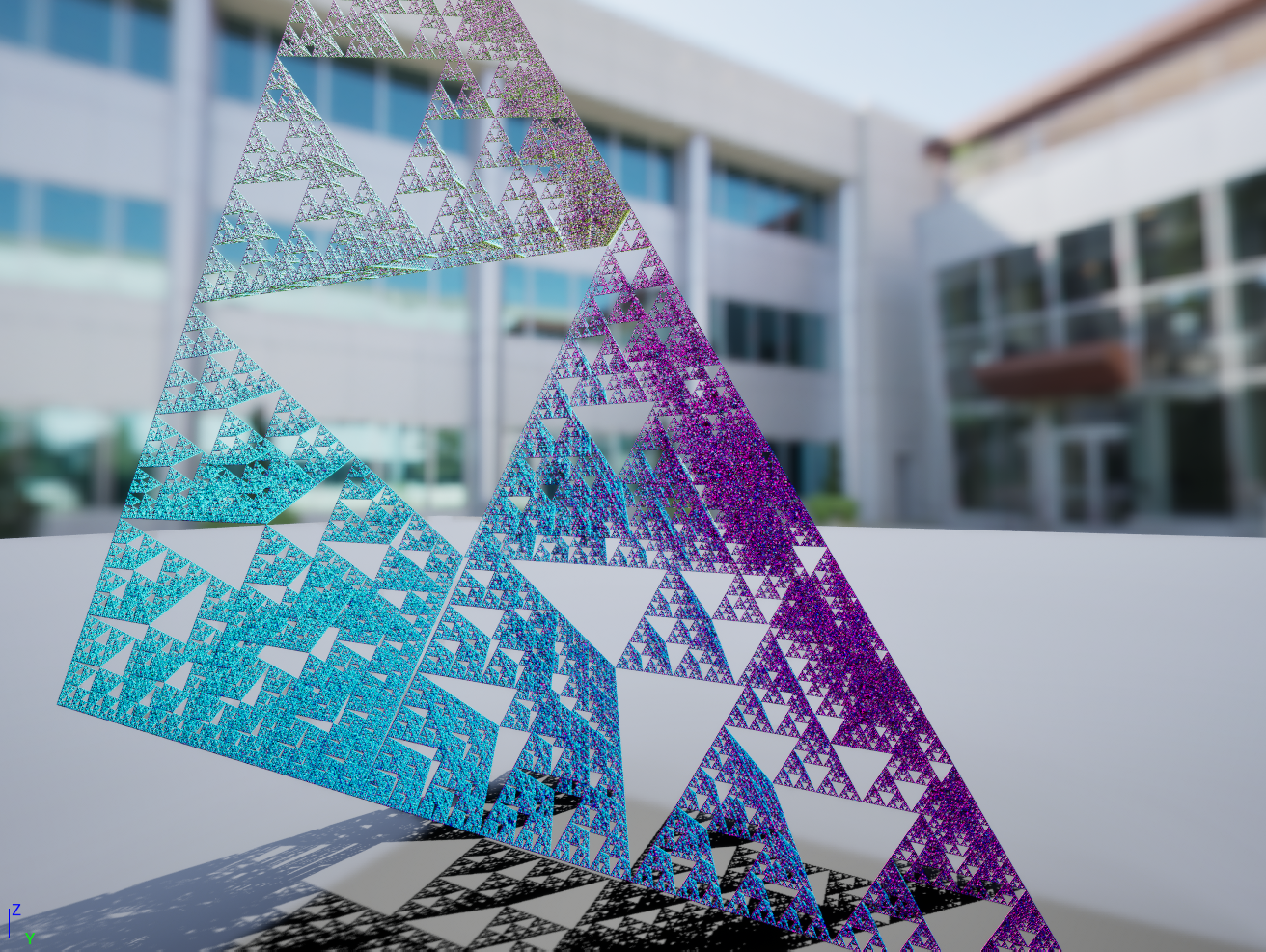
There is more to raymarching here that you can do. For example, your SDF can be subject to smoothing functions, or you can intersect objects with additive or subtractive properties. You can even apply modulus to your SDF to make your object repeat away into infinity. However, I was more interested in exploring how to render clouds.
Volumetric Clouds
Typically, non-solids can be rendered with a fairly simple combination of a “volume” object combined with a 3D texture. However, raymarching allows a lot of fine control over lighting, which seems to be by far the most important factor in the quality of the render.
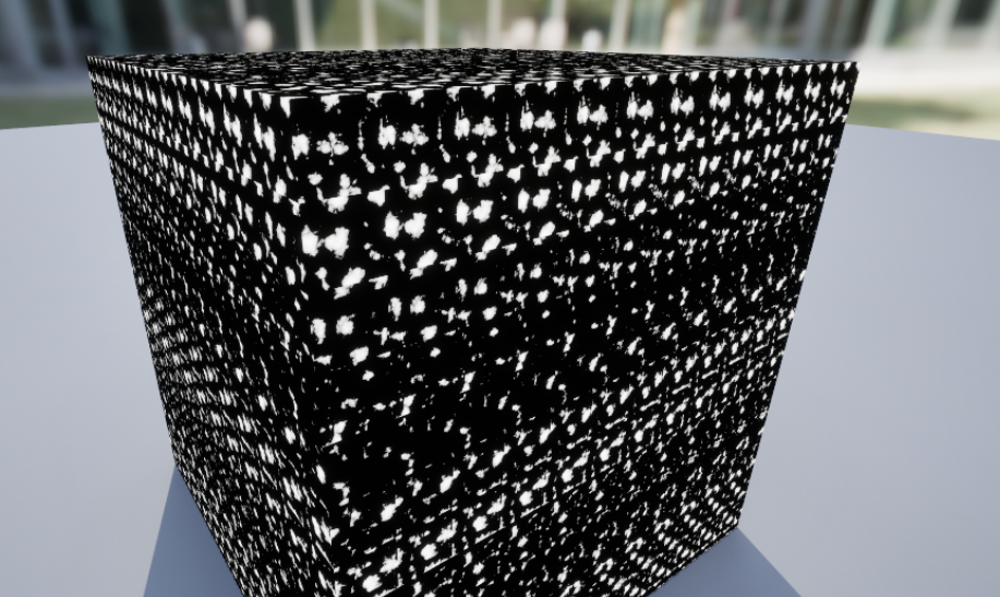
Before we implement lighting, the first thing required is a cloud texture. I haven’t used 3D textures in Unreal yet, so I began with regular 2D Perlin noise.

It appears that 2D textures essentially get cut up into a grid and then stacked up to become a 3D texture, explaining the streaky effect on the side. Therefore, in order to make the noise continuous in 3 dimensions, we need a 2D-tiled texture instead. In any case, this is enough for now to begin setting up volumetric raymarching.

Instead of using SDFs, wwe can do the following: between the entry and exit points of the volume, sample the density in intervals and sum it up to obtain the density through that ray. This allows the calculation of opacity - and then Unreal figures out the rest for us.
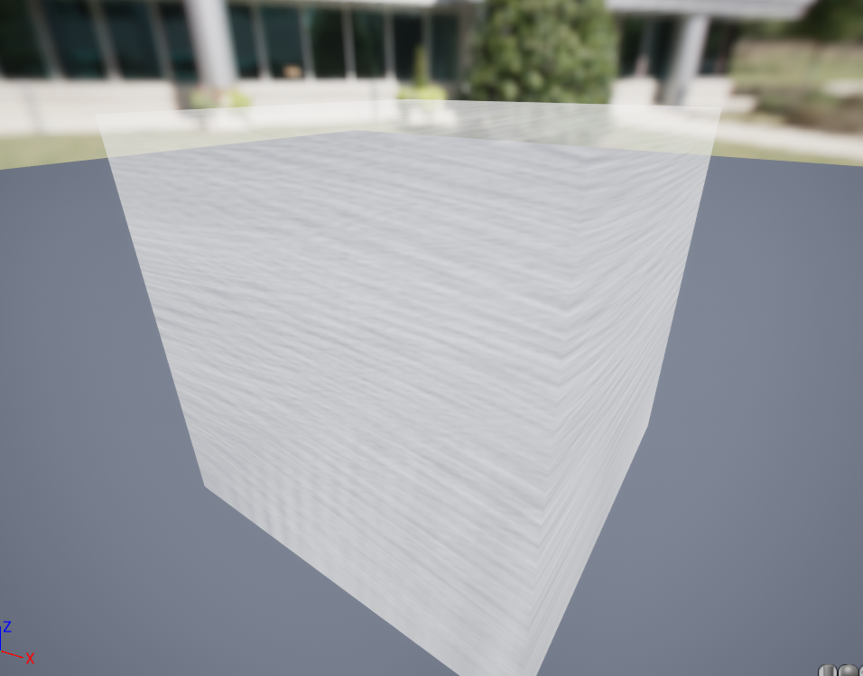 The result was something like this. Clearly, the quality of the texture is terrible and needs to be overhauled. After many iterations, I created a 2D-tiled texture from layered Voronoi noise, with a stronger fall-off to introduce much more empty space.
Finally, I implemented directional lighting. Essentially, from each sampled point along the ray, we cast a new ray towards the directional light, taking more samples until the end of the cloud. This allows us to measure the amount of light emittance at each sampled point along the original ray, and consequently determine the amount of total light along the original ray.
 Adding this to the HLSL code, and using the new texture, we achieve the following result:
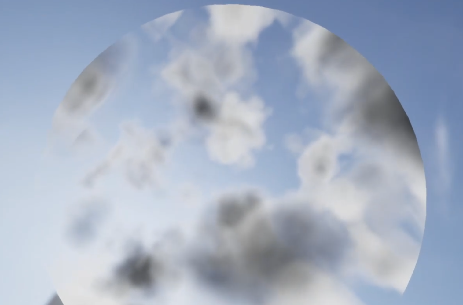 The result is much more cloud-like than previously. I will leave this post here for now - in the future, I hope to explore more realistic models of lighting and combining the previous SDF functions to improve my homebrew clouds.